Big End Bearing Replacement 2023
Background
When new con-rods were fitted (in 2017) the existing big end bearings were re-used. In February 2023 the opportunity was taken to inspect them during the winter overhaul.
Whilst the actual bearing surfaces seemed good, it was clear that the shells had up-and-down clearance in the rods. We decided that new bearings were required.
We believe the original Panhard-manufactured bearings would have been solid bronze. The current bearings were bronze shells lined with white metal. These had been fitted in a major engine overhaul prior to the 1996 London to Brighton run.
If we were to revert to solid bronze it was felt we had the skills within the volunteer team to make them ourselves. If we decided that white-metal lined ones were required then the manufacture would have to be done by a specialist.
We took advice and were told that white metal linings are more forgiving than solid bronze. Lack of clearance or lubrication will lead to potential seizure. Under that circumstance a white metal bearing would melt and give a very noticeable rattle. A solid bronze bearing would lock solid with potentially catastrophic results. If we were to use solid bronze then a greater clearance – suggested at 0.003” (3 thousandths of an inch) on the diameter would be required (for white metal 0.002” clearance would be the aim).
Measurement of the current clearances suggested that we already had 0.004” in the bearings plus whatever clearance there was between the bearings and the rod housing, so noise from the extra clearance was unlikely to be an issue. On grounds of cost and originality the decision was taken to use solid bronze and aim for a clearance of at least 0.004”.
Description of work
All work on car done in the conservation laboratory at the museum
• Crankshaft supported on purpose-made fixtures (made during con-rod replacement work) and sump removed
• Manual assessment of bearing clearance by checking for movement of con-rod relative to crank. Excess clearance
apparent
• Big end caps and bearings removed
• Front cylinder head removed to allow con-rods from cylinders 1 and 2 to be removed (making and checking the
new bearings would be much easier with a con-rod available on the bench, rather than in the engine)
• Each big end crank pin measured with a micrometer in 6 places (on 2 diameters at right angles, and at front,
middle and back of each pin). The condition and roundness of the pins was good, but the pin for No. 2 cylinder
was significantly smaller than the rest – presumably a consequence of the repair work required when this rod had
broken and been replaced sometime in the early history of the car
• The con-rod big end bores were checked and found to be in good condition
• Discussion with Smiths Metals resulted in us specifying SigmaBronze 7 as a suitable material, combining excellent
machinability with good wear resistance and excellent anti-friction properties. This is a material that is available in
a range of cored bars which minimises material waste, and hence cost.
A Team Panhard member with access to the appropriate machinery agreed to make the new bearings, using the
following procedure.
Starting from SigmaBronze 7 hollow bar 51mm outside diameter (OD), 29mm internal diameter (ID)
• Cut blank from bar – 82mm long
• Skim both ends in lathe to square up
• Mark centre line all round
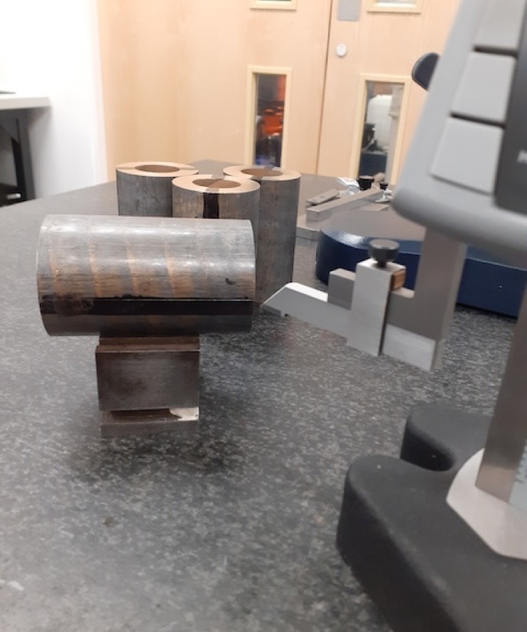
• Split along length using fixture in cut-off bandsaw
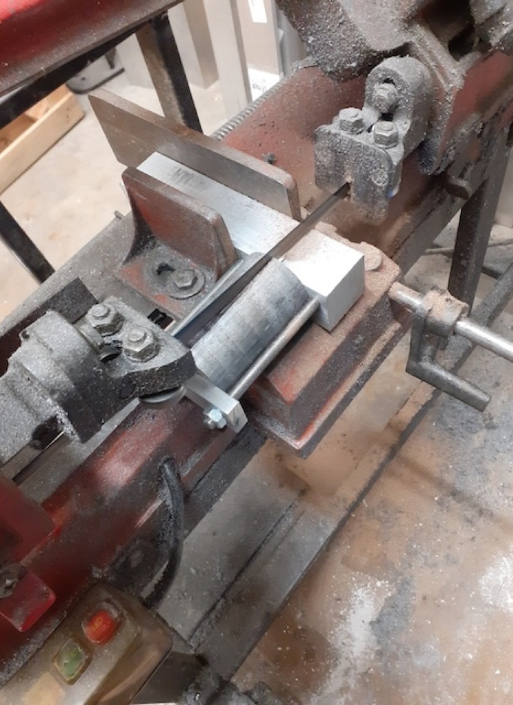
• Face joints in mill
• Use faceplate fixture to grip 2 matching halves
and face end to clean up, turn OD and turn
central recessed section
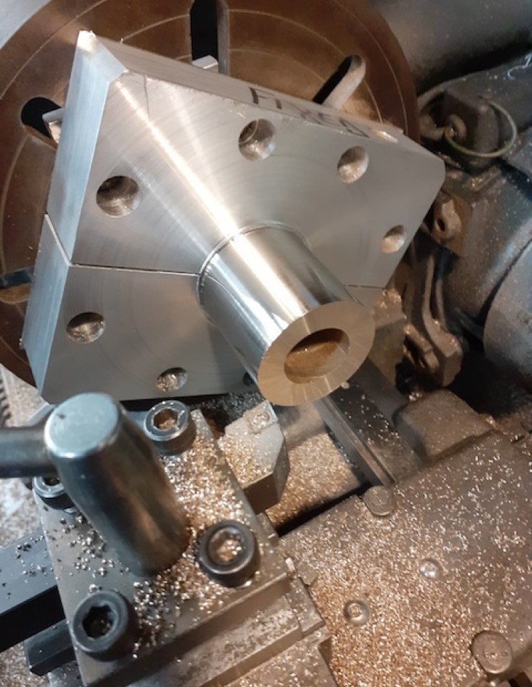
• Fit split clamp to ensure security, then bore ID to leave a reaming allowance
• Ream using floating reamer
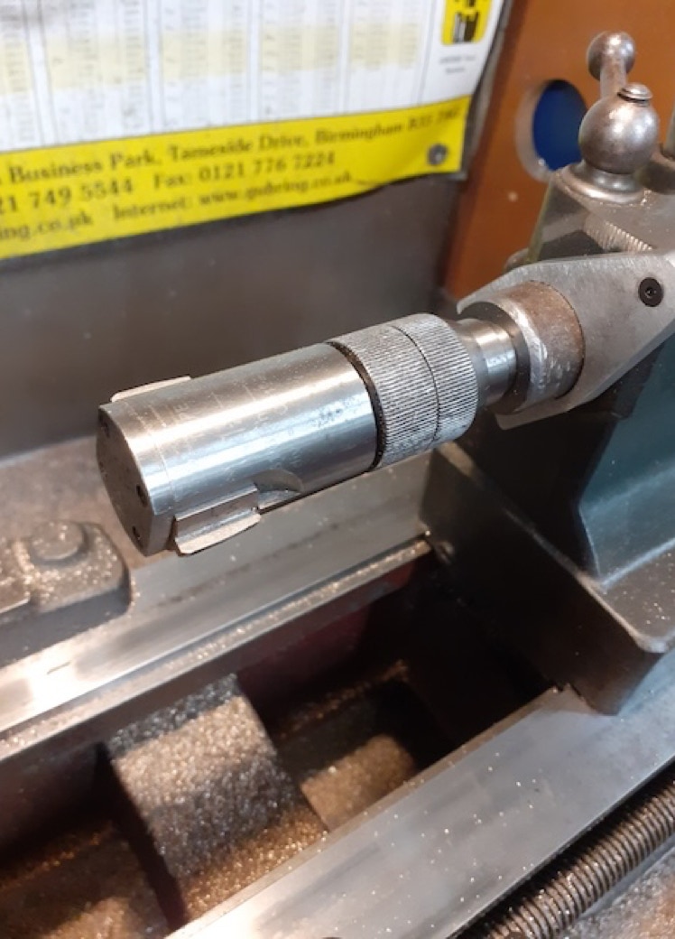
• Chamfer bore and OD at open end
• Remove from faceplate fixture (but leave in split clamp)
and bandsaw off excess
• Use 3-jaw chuck to hold by split clamp and face to
length, turn OD of flange and chamfer bore and OD
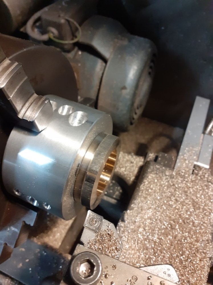
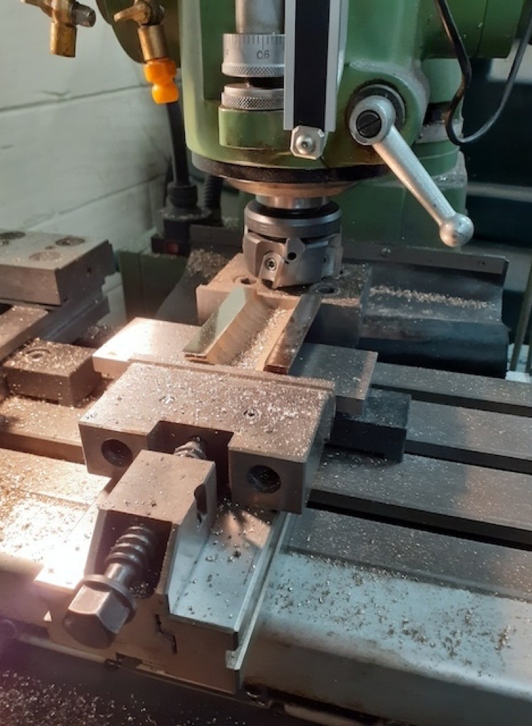
• Whilst still in split jig, mill oil grooves in end faces. Use 45 degree template to align split line and mill with ball end
cutter.
• Drill through in the bolt hole positions (pistol drill)
• Remove from split jig and fit to con-rod to ream bolt holes
• In con-rod with bolts fitted and tightened, check bore using test mandrel turned to minimum allowed size (pin dia +
4 thousandths?). May need more than 1 mandrel if crank pins are different diameters. If there is any binding or out-
of-round distortion, reaming or honing in the con-rod will be necessary. This is easier to do if mud grooves and oil
grooves have not been cut.
• Once bore is satisfactory, drill oil holes using con-rod as jig.
• Stamp cylinder number on each half, plus indication of whether it fits to con-rod or cap.
• Remove to mill mud grooves
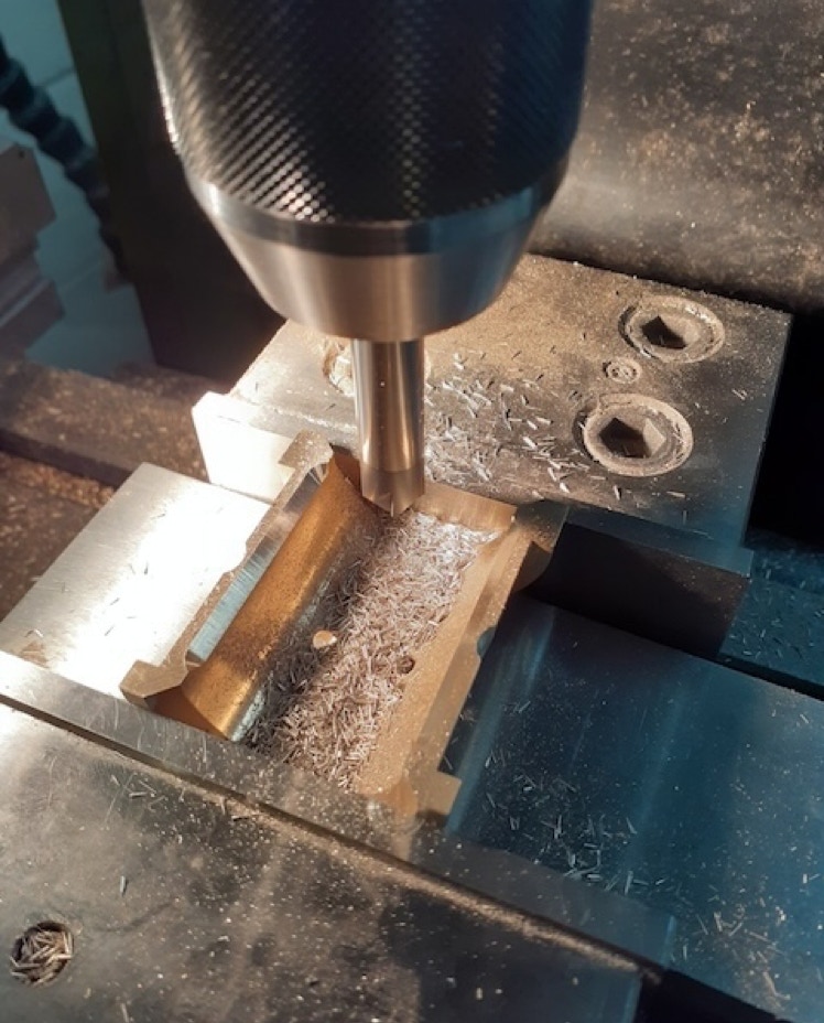
• Use die grinder with small ball ended burr to cut oil
grooves in top half
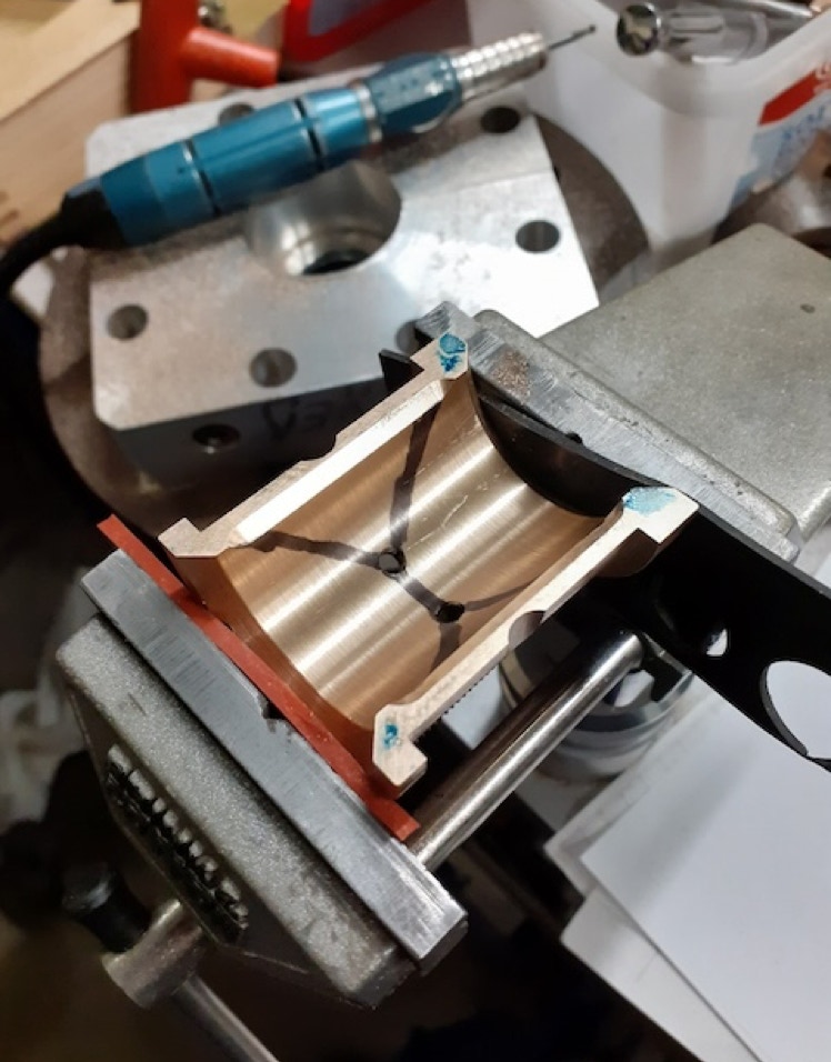
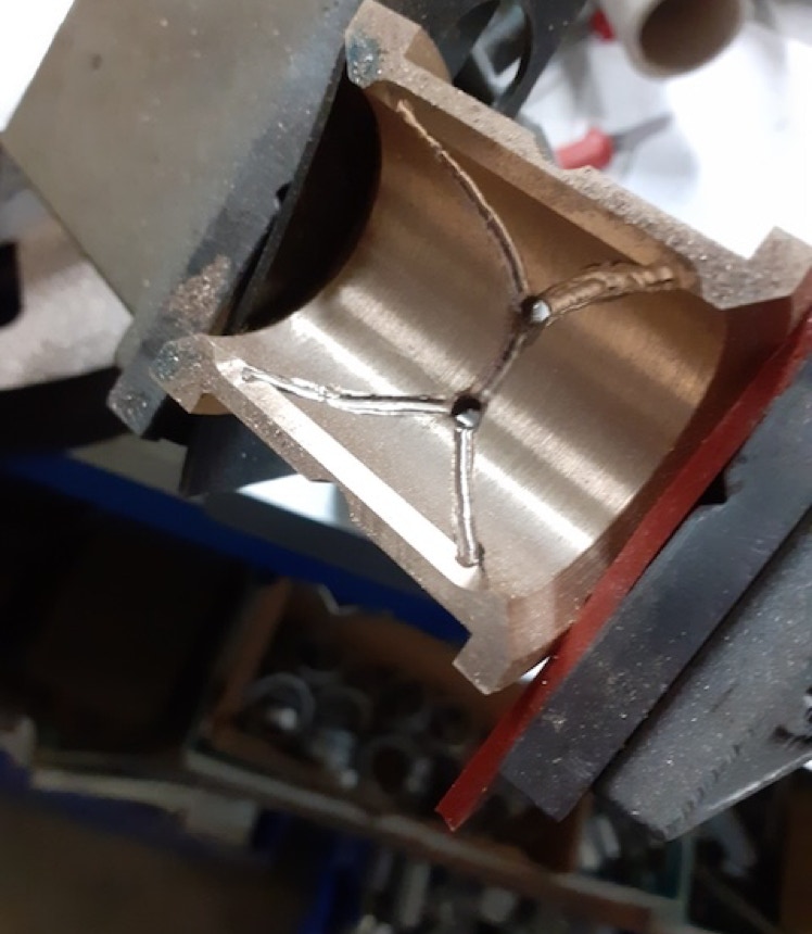
• Deburr and clean.
Page updated
Copyright Team Panhard
2024